UBC Rocket
(2019-Present)
I have been on UBC Rocket's Whistler-Blackcomb Project student design team at the University of British Columbia since September 2019 and am currently working as a co-lead of the Airframe and Internals sub-team as of February 2020. On this sub-team, we are responsible for the design, fabrication, and integration of the aerostructures, airframe, and internal structures of our 100km altitude student-designed space-shot rocket, Whistler-Blackcomb. Whistler-Blackcomb will be 7 meter tall, 30cm diameter, kerosene and liquid oxygen rocket with active cold gas roll control
Passive Stabilizer Fin Prototype
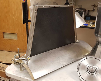
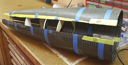
On the Airframe and Internals sub-team, I have had the privilege of being a part of many projects that tackle a wide variety of design challenges and considerations. One of the key aspects I was tasked with was the design, fabrication, and integration of a lightweight, rigid, and heat resistant fin that can withstand the aerodynamic loading of launching Whistler-Blackcomb to the Kármán line. Our first prototype, as seen above, leverages the superb strength to weight ratio of a carbon fiber aluminum honeycomb sandwich as the primary structure. We then bent stainless steel leading and trailing edges to protect the honeycomb panel and to form sharp leading and trailing edges which is preferable at supersonic speeds.
After a series of deflection testing with the first prototype, we concluded that despite the high strength to weight ratio, carbon fiber honeycomb was not suitable for our applications where high torsion in the form of fin flutter was a possibility. As such, I developed an in house aerodynamic flutter calculation program based on the NACA TN4917 method and other research documentation.

Above is a graph of projected velocity at which aeroelastic flutter will occur given parameters derived from the construction and composition of our fin as well as altitude. This is plotted against nominal velocity of the vehicle at that altitude.
After developing the aeroelastic flutter program, I utilized Autodesk Fusion 360s built in topology optimization software to determine key design features of fins with high stiffness-to-weight. I then used these insights along with the calculation sheet and Solidworks static simulations to determine appropriate parameters for the final flight fin and developed a manufacturing model in Solidworks.

Topology optimization study done in Autodesk Fusion 360 used to inform design philosophy
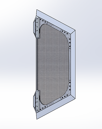
Manufacturing model for the final flight fin design (weight: 1.196kg) with a projected aeroelastic flutter velocity at sea level of Mach 2.38
The final design consists of:
- a milled aluminum frame
- vacuum infused carbon fiber face-plates
- inset aluminum gusset plates
- a low density foam interior to prevent skin flutter
- milled aluminum mounting brackets

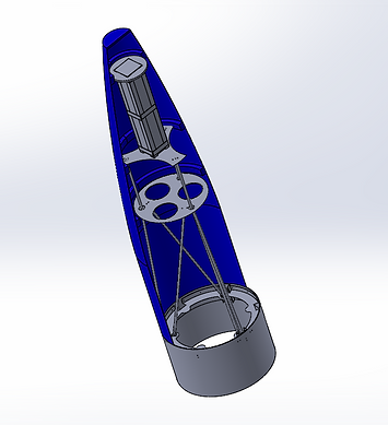
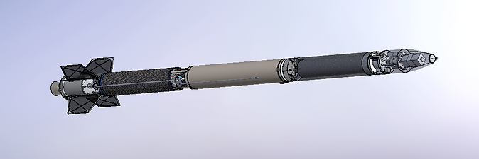
Sub-assembly of the fin can section which will surround the rocket engine and provide passive stabilization and attitude control
Reaction Control Thruster Module Prototype
Although fins are excellent passive stabilizers for a sounding rocket, it is desirable to have a small amount of roll during the powered flight time of the rocket. This is so that any minor inconsistencies in the thrust vector or other unexpected aerodynamic effects can cancel out over time as the rocket slowly rolls in a slight helical path instead of veering wildly off course. As such, we find is necessary to develop an active roll control using cold gas reaction control thrusters. We on the airframe and internals team have taken up the task of designing and developing such a reaction control system.
The design is in it's early stages; however, much work has gone towards simulation and verification and we are ready to begin testing a small scale prototype and its control algorithm.
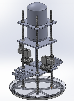
This preliminary design for a dynamic reaction control system test stand will test 2 thrusters in what will be a 4 thruster system for full clockwise/counterclockwise roll control on the flight module
Carbon Fiber Composite Nosecone
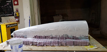
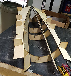
When I first joined the team in September I was lucky enough to work on a half-scale composite nosecone layup test. On the top right is a picture of the nosecone half male mold, made from sculpting foam, MDF sections, and epoxy. It was then filled in with automotive body filler and sanded manually to fit a specified von Kármán curve using a simple laser cut jig I manufactured to fit the curve (below right). The male mold plug was then sprayed with multiple layers of waxed gelcoat and then polished to achieve a smooth surface (below left).
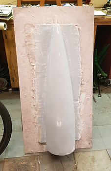

The male plug was then prepped and fiberglass was laid on it to create a female mold (above, pictured next to the original male mold) inside which we would do our composite layups of the half-scale nosecone mould
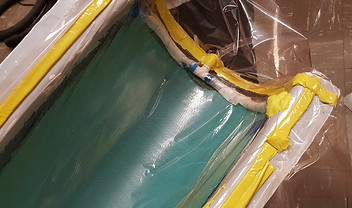
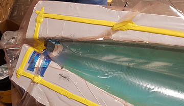
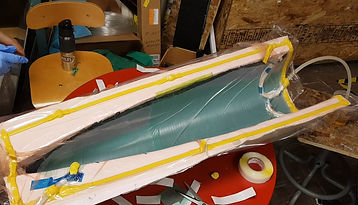
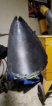
Pictured above are images from our vacuum infusion attempt of the half-scale nosecone prototype. While this was a successful test, we learned valuable information about the manufacturing process of complex composite shapes, and I was tasked with using what we had learned about composite manufacturing to create a new process to improve results for the full scale flight nosecone.
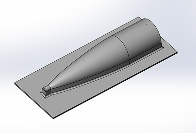
Pictured above is the new and improved male mold plug model which is approximately 2 meters long and planned to be made of CNC milled MDF boards by a facility on-campus. Included in the considerations for the model are the carbon-fiber shrinkage data we gathered from our half-scale testing, as well as additional ease-of-manufacturing features. Instead of a pointed tip for the nosecone, I designed in a cylindrical well to accommodate room for the vacuum infusion apparatus, which we lacked space for in the test. Additionally, a filleted mold and tapered walls allows for easy removal of the finished piece. and extra length on the base allows for space for vacuum infusion tubes to sit without crowding.
Additional Images