Independent Catalyst Project
(2016-2017)


In 2017 my high school rolled out Catalyst, a brand new program aimed at providing the opportunity for seniors to pursue meaningful projects by providing them funding and resources, similar to the style of a university-level capstone program. I was fascinated by human augmentation at the time, and really wanted to pursue a proof-of-concept upper-extremity assistive limb exoskeleton both to gain experience with mechanical design, electrical design, control systems, as well as the whole design and fabrication process from start to finish, including parts acquisition, grant applications, and all the bureaucratic checks to allow a project of this scale to happen at the high school level.
Ultimately, putting 20-30 hours a week into this project over the course of my entire senior year culminated in a 5000USD grant from the Catalyst program which went entirely to the completion of my proof-of-concept design: the SAS-EXO mk.II, named after my high school's namesake in thanks for their generosity.
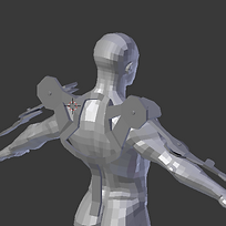
Pictured above (left), is the final product mounted on a mannequin, on display for visitors to the school (I have been told it is a popular destination for showcasing the school). Also pictured (right) is a (somewhat cheesy) advertisement for my high school featuring my project in a popular local magazine that serves primarily American readers in Singapore, The American Club Magazine.
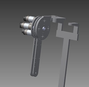


My early designs were conceptually feasible, making use of systems I had seen before, such as a rudimentary planetary gearbox (left), or linear actuator (center), but were ultimately difficult to manufacture, extremely heavy, unnecessarily high power or some combination of the three. After creating preliminary test designs out of spare wood and aluminum, I settle on a vastly lighter, lower power, adjustable frame that would allow me to adjust limb lengths as needed.
Design Challenges:
1. Design a mechanical frame that conforms around the complex movement of the shoulder and torso with minimal compromise of dexterity and strength of the frame
2. Design a lightweight mechanical frame that can be adjusted to fit a range of user proportions
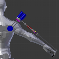
3. Integrate the use of high torque low speed actuators to closely simulate human movement with added mechanical strength
4. Design a closed loop system of actuators that responds to slight movements in the users hand using 3D load cells and rotary encoders as feedback mechanisms


Design Solutions:
1. A 3DOF passively spring-tension support structure around the shoulder joint that conforms to the major movement types a user may experience strain with
2. I used a combination of aluminum T-slot extrusion internals and square tube externals with adjustment pins at half-inch intervals to allow for the accommodation of a range of user sizes. Preliminary designs (right) show the use of long steel carriage bolts as adjustment mechanisms but they proved to be heavier, prone to twisting, and more difficult to manufacture for than the extrusion/square tube system.
3. In order to achieve the desired torque and speed without designing my own gearbox, a resource intensive endeavor, I used COTS high-powered brushed DC car window motors which were of reasonable power and also allowed for a heavy counterweight to the torque arms when actuated to reduce strain on the motor.
4. In order to provide feedback for the motors, I used 1024p/r rotary encoders attached via belt feed to the motors. For user control, I used one 3D load cell per hand in order to get a force vector based on light pressure by the operator. This force vector would then go through a calibration equation and be translated into actuation of the motors, moving the mechanical arms in the same vector direction as the human operator, lending the human operator lifting strength.
Additional Images:


Some additional early stage concept designs in Blender and Autodesk Inventor


Photos of the initial electrical box for bench testing of the hardware